'Ground' Demonstrations of External Occultation Technique
Hodge: 'Ah, so it's a test you're looking for. We don't do tests!'
Tyrian: 'No, of course not. They never do tests. Not many real deeds
either. Oh, conversation with your grandmother's shade in a
darkened room, the odd love potion or two, but comes a doubter, why,
then it's the wrong day, the planets are not in line, the
entrails are not favorable, "we don't do tests"!'
Dragonslayer, 1981
Perhaps those magicians don't do tests, but UMBRANS do!
How is one to test, prior to flight, a planet finding system that requires
a separation of tens of thousands of kilometres between telescope and occulter?
Isn't this impossible?
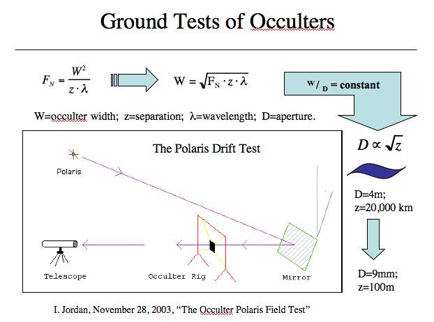
It is not. In fact, one can optically scale the vast system down to something
testable in the lab or in the field. The diagram below shows how one consider's
the scaling problem. To properly scale the system down, certain paramters
need to be preserved. Since an external occulter performs in the far-field
as essentially a narrow-angle interferometer, it is critical to preserve the
wave-nature of the scaled system.
First, one must keep the ratio of the screen width (W)
to telescope diameter (D) the same.
- W / D = Constant1
Next, it is important that the ratio of the apparent size of
the occulter ( W / z ) to the apparent
diffraction scale of the telescope ( &lambda / D )
--where &lambda is the wavelength of light--
be the same as in the space system.
- ( W / z ) / ( &lambda / D ) = Constant2
Substitution of the first equation into the second yields:
- (W2 ) / ( λ z ) = Constant1 * Constant2 = FN
where FN is known as the Fresnel number.
By using these equations, one can scale diffractive optical systems to any size and preserve their
essential optical features.
 The roots of the idea to perform an external occulter test had been around for quite some
time. A. Schultz had been involved in pupil-apodization during
his PhD work and was aware of a NASA funded study of how to detect extrasolar
planets called
Project Orion conducted during the early 1970s. As part of that effort,
scaled testing of an imaging system within a long underground tunnel was performed,
following the general principles outlined above.
The roots of the idea to perform an external occulter test had been around for quite some
time. A. Schultz had been involved in pupil-apodization during
his PhD work and was aware of a NASA funded study of how to detect extrasolar
planets called
Project Orion conducted during the early 1970s. As part of that effort,
scaled testing of an imaging system within a long underground tunnel was performed,
following the general principles outlined above.
At a seminar given in October 2003 by one UMBRAS member (I. Jordan), testing
was discussed extensively after the talk by H. Bond and K. Sahu (AURA)
in the context of attempting to do plane or balloon flight tests of the concept.
At another seminar at the USNO given by R. Lyon (GSFC) a month later, the testing
concept had begun to gel. During the fall, the different scaling regimes were
understood for application to external occulters and one particularly attractive
scaling had been identified.
The Polaris Test
This is exactly what the Westminster Astronomical Society (WASI)
and UMBRAS group members did in 2003/2004
when setting up a demonstration of an external occulter and space telescope system using
amateur astronomical equipment and some inventive craftsmanship. At the WASI website you
can view some of the early photos of the construction and early testing phase.
In December 2004, the WASI-UMBRAS testing concluded.
On Haloween the next year, the WASI-UMBRAS testing team reunited for a photo shoot
and to celebrate the successful conclusion of their optically scaled external
occulter testing efforts.
Below left is the 'telescope site' station. The large C8 merely serves as a platform
to stabilize the NP-101, 540-mm focal length apachromat (which had its aperture masked
way down).

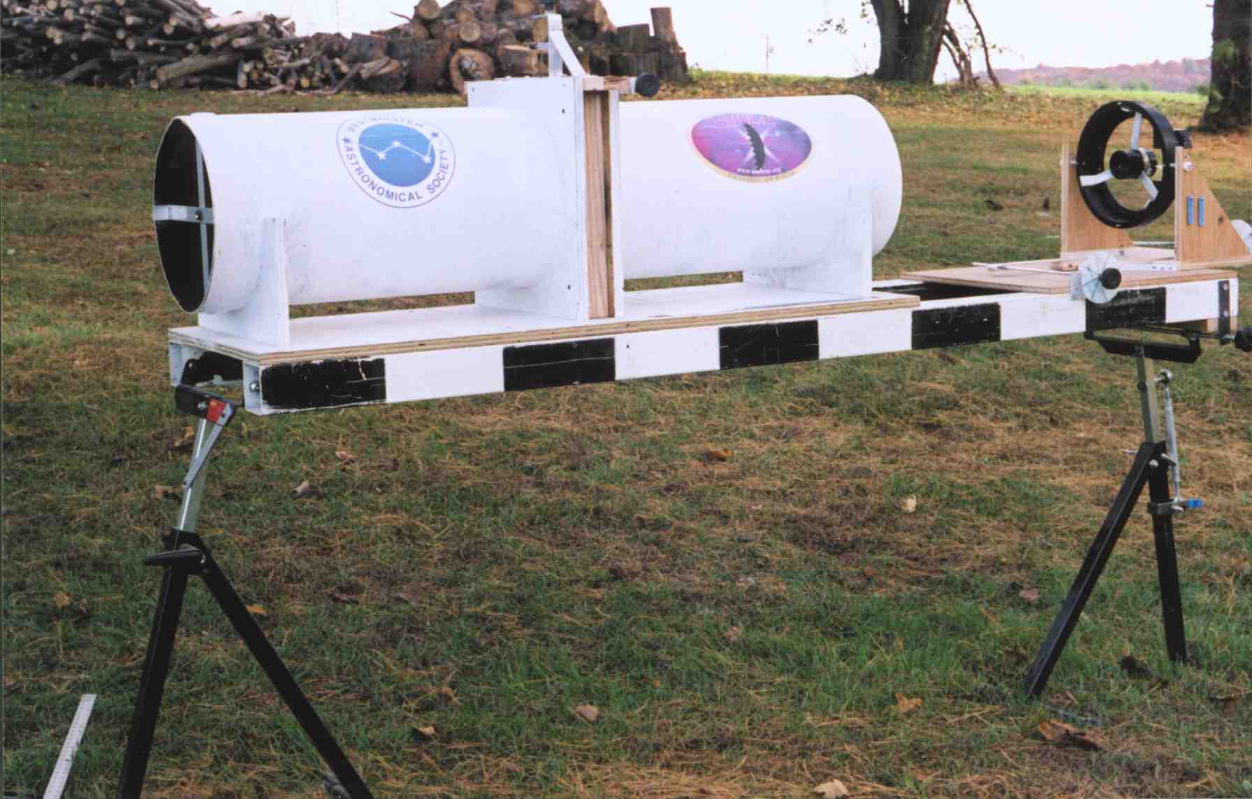
Above right is the optical bench used to shield the external occulter from stray
light and hold the mirror cell (extreme right). A large mirror flat was used to direct
the light from a star (Polaris) past the occulter and toward the distant telescope.
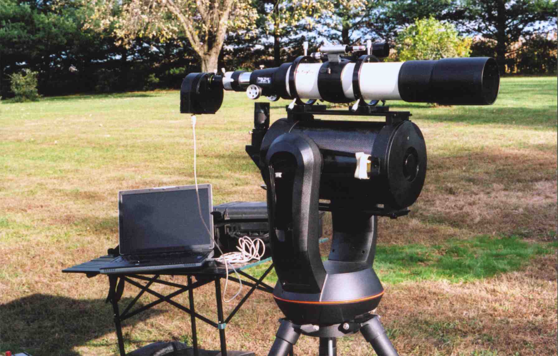
Above left is another view of the telescope and ST7-XME camera used to acquire the
data. The data acquisition computer and table are seen in the background.
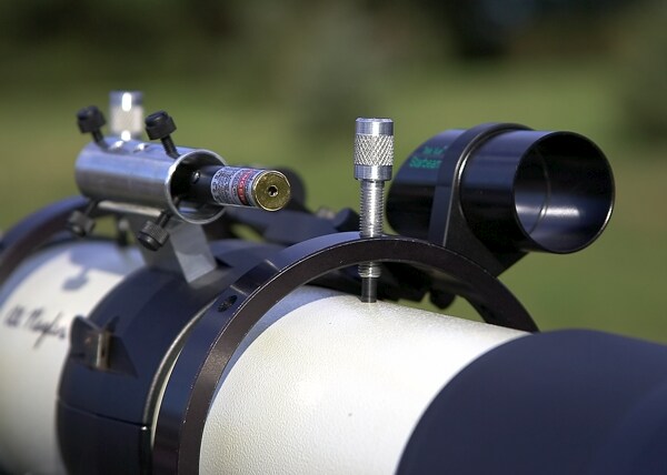
Difficult to see against the background trees, a
green laser was mounted atop the NP-101 which enormously aided alignment on
Polaris. On the right, the laser alignment system is zoomed, appearing to the left of
of the NP-101's finder scope.
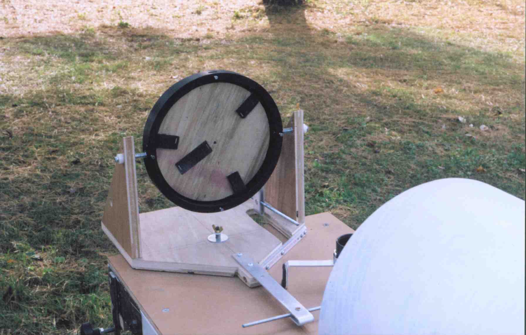
Above is a view of the mirror-mount. An alt-az system driven by hand-screws
allowed the mirror flat to be positioned to either point to the North Star,
or allow the alignment He-Ne laser to demonstrate system collimation. A wooden
blank is shown in place of the mirror used in the tests.
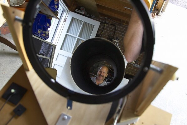
At right, above is what at first may seem to be a
rather confusing picture. The view shows the 10" first-surface
mirror flat (top clipped in the picture) contributed by P. Chen (GSFC)
resting in its mount. The viewing
angle is from above the light shroud at approximately the angle of Polaris.
The view within the mirror
is looking down the light shroud tube (offset circular region). Optical bench
craftsman P. Henze is visible at the end of the light shroud tube that is normally
closest to the telescope.
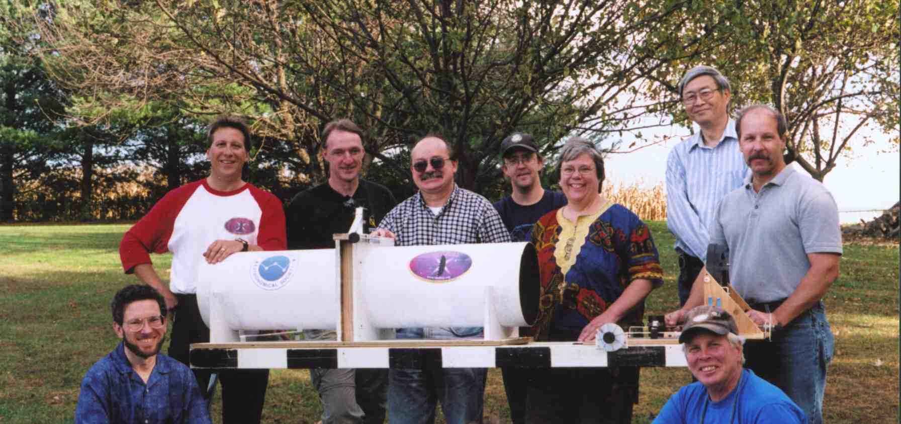
Above is a group photo of most of the individuals involved in the testing. Clockwise
from bottom left: I. Jordan, G. Sauter, M. Kochte, A. Schultz, B. Eney,
H. Hart, P. Chen, P. Henze, R. Smith. (S. Jordan--not directly involved in
the testing but attending the cookout--at bottom center).
In 2005, the New World's team at the U. of Colorado conducted a different
version of the optically scaled ground-demonstration.


